[See all Project Knees – Bike Electrification Project posts]
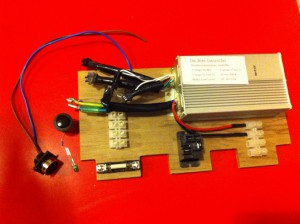
I haven’t posted in a small while, mostly because I’ve been waiting for the batteries to be delivered: a series of mistakes by a UKMail delivery driver meant they took over three weeks to arrive. However, they finally got here, so I could measure up and design the electronics board. The board sits on top of the batteries, with cutouts where the terminals are, and all the electronic bits & bobs will be screwed down to it.
In the meantime, I’ve changed the gear shifter on my left handlebars to be one with a top-mounted lever (rather than under-the-handlebar lever), so there’s room for the thumb throttle to move. I’ve also soldered up the cable that will go from the battery box at the rear of the bike to the throttle and motor at the front.
I also put the batteries in my panniers and cycled home (via nursery) so I could get a feeling for how the weight affected the bike. Apart from the kick-stand not really liking the extra weight, I barely noticed: cycling up Park St (without trailer) felt much the same as normal. This bodes well, I think.
Here are some photos (more for my own reference than anything else).
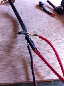
Joining the short cable that comes out of the throttle to my own longer wires:
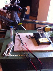
Here’s the throttle mounted on the handlebars. I made the cable up after putting it in place to make sure I got the length right:
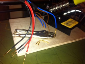
Soldering mains cable to connector pins. Since the connector will only take 10A per pin, and the motor uses 20A per phase, each motor cable gets joined to two pieces of 13A mains cable (brown and blue), which in turn go to the connector pins:
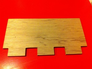
The electronics board, courtesy of Inkscape, a CNC machine, and the ever-helpful Matthew Venn. Matt helped design the box, and every piece (even the simple rectangular sides) has been precision cut using his CNC system. This piece was all my own design though – and yes, the cutouts are meant to be slightly asymmetrical…
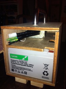
Checking the batteries, board and controller all fit inside the box:
Starting to screw down and connect up the electronics. I think I’m going to put a strip of lighting gel across the cutouts on the lower part of the board to make sure the battery terminals are insulated from the electronics above:
The next step is to connect the batteries together to make the full 36V and test things like the relay (bottom middle), switch and LED (left of the board, ready to be inserted into the front panel). Then I can connect up all the bits and try hooking it into the motor. So far there’s not really been any way to test the throttle wiring: it’s only when it gets power from the controller I’ll be able to see if I’ve soldered the cables up correctly. Nerve-wracking.
Categories
- Atheist Prayer Experiment (1)
- DIY and tinkering (6)
- General ramblings (10)
- Humour (7)
- iPhone (13)
- Watershed techie stuff (6)
Archives
- July 2015 (2)
- March 2013 (2)
- February 2013 (1)
- January 2013 (3)
- September 2012 (1)
- July 2012 (1)
- May 2012 (1)
- November 2011 (1)
- October 2011 (1)
- May 2011 (1)
- March 2011 (2)
- December 2010 (1)
- October 2010 (1)
- July 2010 (1)
- June 2010 (1)
- May 2010 (1)
- March 2010 (1)
- February 2010 (1)
- October 2009 (1)
- July 2009 (1)
- June 2009 (1)
- March 2009 (1)
- July 2008 (2)
- February 2008 (1)
- January 2008 (1)
- December 2007 (2)
- November 2007 (9)
